Cooling Tower
 A hyperboloid cooling tower was patented by Frederik van Iterson and Gerard Kuypers in 1918.
Classification by use
Cooling towers can generally be classified by use into either HVAC (air-conditioning) or industrial duty as suggested by Rantael, Rogellito and Stronghold, April in the book The Mystery of Cooling Towers Unfolded.
HVAC
An HVAC cooling tower is a subcategory rejecting heat from a chiller. Water-cooled chillers are normally more energy efficient than air-cooled chillers due to heat rejection to tower water at or near wet-bulb temperatures. Air-cooled chillers must reject heat at the dry-bulb temperature, and thus have a lower average reverse-Carnot cycle effectiveness. Large office buildings, hospitals, and schools typically use one or more cooling towers as part of their air conditioning systems. Generally, industrial cooling towers are much larger than HVAC towers.
HVAC use of a cooling tower pairs the cooling tower with a water-cooled chiller or water-cooled condenser. A ton of air-conditioning is the removal of 12,000 Btu/hour (3517 W). The equivalent ton on the cooling tower side actually rejects about 15,000 Btu/hour (4396 W) due to the heat-equivalent of the energy needed to drive the chiller's compressor. This equivalent ton is defined as the heat rejection in cooling 3 U.S. gallons/minute (1,500 pound/hour) of water 10 °F (5.56 °C), which amounts to 15,000 Btu/hour, or a chiller coefficient-of-performance (COP) of 4.0. This COP is equivalent to an energy efficiency ratio (EER) of 13.65.
Industrial cooling towers can be used to remove heat from various sources such as machinery or heated process material. The primary use of large, industrial cooling towers is to remove the heat absorbed in the circulating cooling water systems used in power plants, petroleum refineries, petrochemical plants, natural gas processing plants, food processing plants, semi-conductor plants, and other industrial facilities. The circulation rate of cooling water in a typical 700 MW coal-fired power plant with a cooling tower amounts to about 71,600 cubic metres an hour (315,000 U.S. gallons per minute) and the circulating water requires a supply water make-up rate of perhaps 5 percent (i.e., 3,600 cubic metres an hour).
If that same plant had no cooling tower and used once-through cooling water, it would require about 100,000 cubic metres an hour [4] and that amount of water would have to be continuously returned to the ocean, lake or river from which it was obtained and continuously re-supplied to the plant. Furthermore, discharging large amounts of hot water may raise the temperature of the receiving river or lake to an unacceptable level for the local ecosystem. Elevated water temperatures can kill fish and other aquatic organisms. A cooling tower serves to dissipate the heat into the atmosphere instead and wind and air diffusion spreads the heat over a much larger area than hot water can distribute heat in a body of water. Some coal-fired and nuclear power plants located in coastal areas do make use of once-through ocean water. But even there, the offshore discharge water outlet requires very careful design to avoid environmental problems.
Petroleum refineries also have very large cooling tower systems. A typical large refinery processing 40,000 metric tonnes of crude oil per day (300,000 barrels per day) circulates about 80,000 cubic metres of water per hour through its cooling tower system.
The world's tallest cooling tower is the 200 metre tall cooling tower of Niederaussem Power Plant.
Cooling Tower Heat transfer methods
With respect to the heat transfer mechanism employed, the main types are:
- Wet cooling towers or simply cooling towers operate on the principle of evaporation. The working fluid and the evaporated fluid (usually H2O) are one and the same.
- Dry coolers operate by heat transfer through a surface that separates the working fluid from ambient air, such as in a heat exchanger, utilizing convective heat transfer. They do not use evaporation.
- Fluid coolers are hybrids that pass the working fluid through a tube bundle, upon which clean water is sprayed and a fan-induced draft applied. The resulting heat transfer performance is much closer to that of a wet cooling tower, with the advantage provided by a dry cooler of protecting the working fluid from environmental exposure.
In a wet cooling tower, the warm water can be cooled to a temperature lower than the ambient air dry-bulb temperature, if the air is relatively dry. As ambient air is drawn past a flow of water, evaporation occurs. Evaporation results in saturated air conditions, lowering the temperature of the water to the wet bulb air temperature, which is lower than the ambient dry bulb air temperature, the difference determined by the humidity of the ambient air.
To achieve better performance (more cooling), a medium called fill is used to increase the surface area between the air and water flows. Splash fill consists of material placed to interrupt the water flow causing splashing. Film fill is composed of thin sheets of material upon which the water flows. Both methods create increased surface area.
Air flow generation methods
With respect to drawing air through the tower, there are three types of cooling towers:
- Natural draft, which utilizes buoyancy via a tall chimney. Warm, moist air naturally rises due to the density differential to the dry, cooler outside air. Warm moist air is less dense than drier air at the same pressure. This moist air buoyancy produces a current of air through the tower.
- Mechanical draft, which uses power driven fan motors to force or draw air through the tower.
- Induced draft: A mechanical draft tower with a fan at the discharge which pulls air through tower. The fan induces hot moist air out the discharge. This produces low entering and high exiting air velocities, reducing the possibility of recirculation in which discharged air flows back into the air intake. This fan/fin arrangement is also known as draw-through. (see Image 2, 3)
- Forced draft: A mechanical draft tower with a blower type fan at the intake. The fan forces air into the tower, creating high entering and low exiting air velocities. The low exiting velocity is much more susceptible to recirculation. With the fan on the air intake, the fan is more susceptible to complications due to freezing conditions. Another disadvantage is that a forced draft design typically requires more motor horsepower than an equivalent induced draft design. The forced draft benefit is its ability to work with high static pressure. They can be installed in more confined spaces and even in some indoor situations. This fan/fill geometry is also known as blow-through. (see Image 4)
- Fan assisted natural draft. A hybrid type that appears like a natural draft though airflow is assisted by a fan.
Hyperboloid (hyperbolic) cooling towers have become the design standard for all natural-draft cooling towers because of their structural strength and minimum usage of material. The hyperboloid shape also aids in accelerating the upward convective air flow, improving cooling efficiency. They are popularly associated with nuclear power plants. However, this association is misleading, as the same kind of cooling towers are often used at large coal-fired power plants as well. Similarly, not all nuclear power plants have cooling towers, instead cooling their heat exchangers with lake, river or ocean water.
Categorization by air-to-water flow
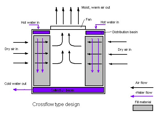
Crossflow
Crossflow is a design in which the air flow is directed perpendicular to the water flow (see diagram below). Air flow enters one or more vertical faces of the cooling tower to meet the fill material. Water flows (perpendicular to the air) through the fill by gravity. The air continues through the fill and thus past the water flow into an open plenum area. A distribution or hot water basin consisting of a deep pan with holes or nozzles in the bottom is utilized in a crossflow tower. Gravity distributes the water through the nozzles uniformly across the fill material.
Counterflow
In a counterflow design the air flow is directly opposite to the water flow (see diagram below). Air flow first enters an open area beneath the fill media and is then drawn up vertically. The water is sprayed through pressurized nozzles and flows downward through the fill, opposite to the air flow.

Common to both designs:
- The interaction of the air and water flow allow a partial equalization and evaporation of water.
- The air, now saturated with water vapor, is discharged from the cooling tower.
- A collection or cold water basin is used to contain the water after its interaction with the air flow.
Both crossflow and counterflow designs can be used in natural draft and mechanical draft cooling towers.
Cooling tower as a flue gas stack
At some modern power plants, equipped with flue gas purification like the Power Station Staudinger Grosskrotzenburg and the Power Station Rostock, the cooling tower is also used as a flue gas stack (industrial chimney). At plants without flue gas purification, problems with corrosion may occur.
Wet cooling tower material balance
Quantitatively, the material balance around a wet, evaporative cooling tower system is governed by the operational variables of makeup flow rate, evaporation and windage losses, draw-off rate, and the concentration cycles:

| M | = Make-up water in m³/h |
| C | = Circulating water in m³/h |
| D | = Draw-off water in m³/h |
| E | = Evaporated water in m³/h |
| W | = Windage loss of water in m³/h |
| X | = Concentration in ppmw (of any completely soluble salts … usually chlorides) |
| XM | = Concentration of chlorides in make-up water (M), in ppmw |
| XC | = Concentration of chlorides in circulating water (C), in ppmw |
| Cycles | = Cycles of concentration = XC / XM (dimensionless) |
| ppmw | = parts per million by weight |
In the above sketch, water pumped from the tower basin is the cooling water routed through the process coolers and condensers in an industrial facility. The cool water absorbs heat from the hot process streams which need to be cooled or condensed, and the absorbed heat warms the circulating water (C). The warm water returns to the top of the cooling tower and trickles downward over the fill material inside the tower. As it trickles down, it contacts ambient air rising up through the tower either by natural draft or by forced draft using large fans in the tower. That contact causes a small amount of the water to be lost as windage (W) and some of the water (E) to evaporate. The heat required to evaporate the water is derived from the water itself, which cools the water back to the original basin water temperature and the water is then ready to recirculate. The evaporated water leaves its dissolved salts behind in the bulk of the water which has not been evaporated, thus raising the salt concentration in the circulating cooling water. To prevent the salt concentration of the water from becoming too high, a portion of the water is drawn off (D) for disposal. Fresh water makeup (M) is supplied to the tower basin to compensate for the loss of evaporated water, the windage loss water and the draw-off water.
A water balance around the entire system is:
- M = E + D + W
Since the evaporated water (E) has no salts, a chloride balance around the system is:
- M (XM) = D (XC) + W (XC) = XC (D + W)
and, therefore:
- XC / XM = Cycles of concentration = M ÷ (D + W) = M ÷ (M – E) = 1 + [E ÷ (D + W)]
From a simplified heat balance around the cooling tower:
- E = C · ΔT · cp ÷ HV
| where: | |
| HV | = latent heat of vaporization of water = ca. 2260 kJ / kg |
| ΔT | = water temperature difference from tower top to tower bottom, in °C |
| cp | = specific heat of water = ca. 4.184 kJ / (kg °C) °C) |
Windage (or drift) losses (W) from large-scale industrial cooling towers, in the absence of manufacturer's data, may be assumed to be:
- W = 0.3 to 1.0 percent of C for a natural draft cooling tower without windage drift eliminators
- W = 0.1 to 0.3 percent of C for an induced draft cooling tower without windage drift eliminators
- W = about 0.005 percent of C (or less) if the cooling tower has windage drift eliminators
Cycles of concentration represents the accumulation of dissolved minerals in the recirculating cooling water. Draw-off (or blowdown) is used principally to control the buildup of these minerals.
The chemistry of the makeup water including the amount of dissolved minerals can vary widely. Makeup waters low in dissolved minerals such as those from surface water supplies (lakes, rivers etc.) tend to be aggressive to metals (corrosive). Makeup waters from ground water supplies (wells) are usually higher in minerals and tend to be scaling (deposit minerals). Increasing the amount of minerals present in the water by cycling can make water less aggressive to piping however excessive levels of minerals can cause scaling problems.
As the cycles of concentration increase the water may not be able to hold the minerals in solution. When the solubility of these minerals have been exceeded they can precipitate out as mineral solids and cause fouling and heat exchange problems in the cooling tower or the heat exchangers. The temperatures of the recirculating water, piping and heat exchange surfaces determine if and where minerals will precipitate from the recirculating water. Often a professional water treatment consultant will evaluate the makeup water and the operating conditions of the cooling tower and recommend an appropriate range for the cycles of concentration. The use of water treatment chemicals, pretreatment such as water softening, pH adjustment, and other techniques can affect the acceptable range of cycles of concentration.
Concentration cycles in the majority of cooling towers usually range from 3 to 7. In the United States the majority of water supplies are well waters and have significant levels of dissolved solids. On the other hand one of the largest water supplies, New York City, has a surface supply quite low in minerals and cooling towers in that city are often allowed to concentrate to 7 or more cycles of concentration.
Besides treating the circulating cooling water in large industrial cooling tower systems to minimize scaling and fouling, the water should be filtered and also be dosed with biocides and algaecides to prevent growths that could interfere with the continuous flow of the water. For closed loop evaporative towers, corrosion inhibitors may be used, but caution should be taken to meet local environmental regulations as some inhibitors use chromates.
Ambient conditions dictate the efficiency of any given tower due to the amount of water vapor the air is able to absorb and hold, as can be determined on a psychrometric chart.
Cooling Tower Operation In Freezing Weather
Cooling towers with malfunctions can freeze during very cold weather. Typically, freezing starts at the corners of a cooling tower with a reduced or absent heat load. Increased freezing conditions can create growing volumes of ice, resulting in increased structural loads. During the winter, some sites continuously operate cooling towers with 40 °F (4 °C) water leaving the tower. Basin heaters, tower draindown, and other freeze protection methods are often employed in cold climates.
- Do not operate the tower unattended.
- Do not operate the tower without a heat load. This can include basin heaters and heat trace. Basin heaters maintain the temperature of the water in the tower pan at an acceptable level. Heat trace is a resistive element that runs along water pipes located in cold climates to prevent freezing.
- Maintain design water flow rate over the fill.
- Manipulate airflow to maintain water temperature above freezing point.
Some commonly used terms in the cooling tower industry
- Drift - Water droplets that are carried out of the cooling tower with the exhaust air. Drift droplets have the same concentration of impurities as the water entering the tower. The drift rate is typically reduced by employing baffle-like devices, called drift eliminators, through which the air must travel after leaving the fill and spray zones of the tower.
- Blow-out - Water droplets blown out of the cooling tower by wind, generally at the air inlet openings. Water may also be lost, in the absence of wind, through splashing or misting. Devices such as wind screens, louvers, splash deflectors and water diverters are used to limit these losses.
- Plume - The stream of saturated exhaust air leaving the cooling tower. The plume is visible when water vapor it contains condenses in contact with cooler ambient air, like the saturated air in one's breath fogs on a cold day. Under certain conditions, a cooling tower plume may present fogging or icing hazards to its surroundings. Note that the water evaporated in the cooling process is "pure" water, in contrast to the very small percentage of drift droplets or water blown out of the air inlets.
- Blow-down - The portion of the circulating water flow that is removed in order to maintain the amount of dissolved solids and other impurities at an acceptable level. It may be noted that higher TDS (total dissolved solids) concentration in solution results in greater potential cooling tower efficiency. However the higher the TDS concentration, the greater the risk of scale, biological growth and corrosion.
- Leaching - The loss of wood preservative chemicals by the washing action of the water flowing through a wood structure cooling tower.
- Noise - Sound energy emitted by a cooling tower and heard (recorded) at a given distance and direction. The sound is generated by the impact of falling water, by the movement of air by fans, the fan blades moving in the structure, and the motors, gearboxes or drive belts.
- Approach - The approach is the difference in temperature between the cooled-water temperature and the entering-air wet bulb temperature (twb). Since the cooling towers are based on the principles of evaporative cooling, the maximum cooling tower efficiency depends on the wet bulb temperature of the air. The wet-bulb temperature is a type of temperature measurement that reflects the physical properties of a system with a mixture of a gas and a vapor, usually air and water vapor
- Range - The range is the temperature difference between the water inlet and water exit.
- Fill - Inside the tower, fills are added to increase contact surface as well as contact time between air and water. Thus they provide better heat transfer. The efficiency of the tower also depends on them. There are two types of fills that may be used:
- Film type fill (causes water to spread into a thin film)
- Splash type fill (breaks up water and interrupts its vertical progress)
Fire hazards
Cooling towers which are constructed in whole or in part of combustible materials can support propagating internal fires. The resulting damage can be sufficiently severe to require the replacement of the entire cell or tower structure. For this reason, some codes and standards recommend combustible cooling towers be provided with an automatic fire sprinkler system. Fires can propagate internally within the tower structure during maintenance when the cell is not in operation (such as for maintenance or construction), and even when the tower is in operation, especially those of the induced-draft type because of the existence of relatively dry areas within the towers.
Stability
Being very large structures, they are susceptible to wind damage, and several spectacular failures have occurred in the past. At Ferrybridge power station on 1 November 1965, the station was the site of a major structural failure, when three of the cooling towers collapsed due to vibrations in 85mph winds. Although the structures had been built to withstand higher wind speeds, the shape of the cooling towers meant that westerly winds were funnelled into the towers themselves, creating a vortex. Three out of the original eight cooling towers were destroyed and the remaining five were severely damaged. The towers were rebuilt and all eight cooling towers were strengthened to tolerate adverse weather conditions. Building codes were changed to include improved structural support, and wind tunnel tests introduced to check tower structures and configuration.
Steam Turbine use in a Power Plant
It has almost completely replaced the reciprocating piston steam engine primarily because of its greater thermal efficiency and higher power-to-weight ratio. Because the turbine generates rotary motion, it is particularly suited to be used to drive an electrical generator – about 80% of all electricity generation in the world is by use of steam turbines. The steam turbine is a form of heat engine that derives much of its improvement in thermodynamic efficiency through the use of multiple stages in the expansion of the steam, which results in a closer approach to the ideal reversible process.

Types of Steam Turbine
Steam turbines are made in a variety of sizes ranging from small <1 style="font-size:130%;">
Steam Supply and Exhaust Condition
These types include condensing, noncondensing, reheat, extraction and induction.
Noncondensing or backpressure turbines are most widely used for process steam applications. The exhaust pressure is controlled by a regulating valve to suit the needs of the process steam pressure. These are commonly found at refineries, district heating units, pulp and paper plants, and desalination facilities where large amounts of low pressure process steam are available.
Condensing turbines are most commonly found in electrical power plants. These turbines exhaust steam in a partially condensed state, typically of a quality near 90%, at a pressure well below atmospheric to a condenser.
Reheat turbines are also used almost exclusively in electrical power plants. In a reheat turbine, steam flow exits from a high pressure section of the turbine and is returned to the boiler where additional superheat is added. The steam then goes back into an intermediate pressure section of the turbine and continues its expansion.
Extracting type turbines are common in all applications. In an extracting type turbine, steam is released from various stages of the turbine, and used for industrial process needs or sent to boiler feedwater heaters to improve overall cycle efficiency. Extraction flows may be controlled with a valve, or left uncontrolled.
Induction turbines introduce low pressure steam at an intermediate stage to produce additional power.
Casing or Shaft Arrangements
These arrangements include single casing, tandem compound and cross compound turbines. Single casing units are the most basic style where a single casing and shaft are coupled to a generator. Tandem compound are used where two or more casings are directly coupled together to drive a single generator. A cross compound turbine arrangement features two or more shafts not in line driving two or more generators that often operate at different speeds. A cross compound turbine is typically used for many large applications.
Principle of Operation and Design
 An ideal steam turbine is considered to be an isentropic process, or constant entropy process, in which the entropy of the steam entering the turbine is equal to the entropy of the steam leaving the turbine. No steam turbine is truly “isentropic”, however, with typical isentropic efficiencies ranging from 20%-90% based on the application of the turbine. The interior of a turbine comprises several sets of blades, or “buckets” as they are more commonly referred to. One set of stationary blades is connected to the casing and one set of rotating blades is connected to the shaft. The sets intermesh with certain minimum clearances, with the size and configuration of sets varying to efficiently exploit the expansion of steam at each stage.
Turbine efficiency
To maximize turbine efficiency the steam is expanded, generating work, in a number of stages. These stages are characterized by how the energy is extracted from them and are known as either impulse or reaction turbines. Most steam turbines use a mixture of the reaction and impulse designs: each stage behaves as either one or the other, but the overall turbine uses both. Typically, higher pressure sections are impulse type and lower pressure stages are reaction type.
Impulse turbines
An impulse turbine has fixed nozzles that orient the steam flow into high speed jets. These jets contain significant kinetic energy, which the rotor blades, shaped like buckets, convert into shaft rotation as the steam jet changes direction. A pressure drop occurs across only the stationary blades, with a net increase in steam velocity across the stage.
As the steam flows through the nozzle its pressure falls from inlet pressure to the exit pressure (atmospheric pressure, or more usually, the condenser vacuum). Due to this higher ratio of expansion of steam in the nozzle the steam leaves the nozzle with a very high velocity. The steam leaving the moving blades is a large portion of the maximum velocity of the steam when leaving the nozzle. The loss of energy due to this higher exit velocity is commonly called the "carry over velocity" or "leaving loss".
Reaction turbines
In the reaction turbine, the rotor blades themselves are arranged to form convergent nozzles. This type of turbine makes use of the reaction force produced as the steam accelerates through the nozzles formed by the rotor. Steam is directed onto the rotor by the fixed vanes of the stator. It leaves the stator as a jet that fills the entire circumference of the rotor. The steam then changes direction and increases its speed relative to the speed of the blades. A pressure drop occurs across both the stator and the rotor, with steam accelerating through the stator and decelerating through the rotor, with no net change in steam velocity across the stage but with a decrease in both pressure and temperature, reflecting the work performed in the driving of the rotor.
Operation and Maintenance of Steam Turbine
When warming up a steam turbine for use, the main steam stop valves (after the boiler) have a bypass line to allow superheated steam to slowly bypass the valve and proceed to heat up the lines in the system along with the steam turbine. Also a turning gear is engaged when there is no steam to the turbine to slowly rotate the turbine to ensure even heating to prevent uneven expansion. After first rotating the turbine by the turning gear, allowing time for the rotor to assume a straight plane (no bowing), then the turning gear is disengaged and steam is admitted to the turbine, first to the astern blades then to the ahead blades slowly rotating the turbine at 10 to 15 RPM to slowly warm the turbine.
Problems with turbines are now rare and maintenance requirements are relatively small. Any imbalance of the rotor can lead to vibration, which in extreme cases can lead to a blade letting go and punching straight through the casing. It is, however, essential that the turbine be turned with dry steam. If water gets into the steam and is blasted onto the blades (moisture carryover) rapid impingement and erosion of the blades can occur, possibly leading to imbalance and catastrophic failure. Also, water entering the blades will likely result in the destruction of the thrust bearing for the turbine shaft. To prevent this, along with controls and baffles in the boilers to ensure high quality steam, condensate drains are installed in the steam piping leading to the turbine.
Speed regulation
The control of a turbine with a governor is essential, as turbines need to be run up slowly, to prevent damage while some applications (such as the generation of alternating current electricity) require precise speed control. Uncontrolled acceleration of the turbine rotor can lead to an overspeed trip, which causes the nozzle valves that control the flow of steam to the turbine to close. If this fails then the turbine may continue accelerating until it breaks apart, often spectacularly. Turbines are expensive to make, requiring precision manufacture and special quality materials. During normal operation in synchronization with the electricity net powerplants are governed with a five percent droop speed control . This means the full load speed is 100% and the no load speed is 105%. This is required for the stable operation of the net without hunting and dropouts of powerplants. Normally the changes in speed are minor . Adjustments in power output are made by slowly raising the droop curve by increasing the spring pressure on a centrifugal governor. Generally this is a basic system requirement for all powerplants because the older and newer plants have to be compatible in response to the instantaneous changes in frequency without depending on outside communication.
Direct drive
Electrical power plants use large steam turbines driving electric generators to produce most (about 80%) of the world's electricity. Most of these centralised stations are of two types, fossil fuel power plants and nuclear power plants, but some countries are using concentrating solar power (CSP) to create the steam. Steam turbines can also be used directly to drive large centrifugal pumps, such as feedwater pumps at a thermal power plant.
It has been proposed that, given sufficient solar energy, silicon might be refined for use as a coal replacement for this type of engine.
The turbines used for electric power generation are most often directly coupled to their generators. As the generators must rotate at constant synchronous speeds according to the frequency of the electric power system, the most common speeds are 3000 r/min for 50 Hz systems, and 3600 r/min for 60 Hz systems. In installations with high steam output, as may be found in nuclear power plant, the generator sets may be arranged to operate at half these speeds, but with four-pole generators.
Power Plant
Power plant is also used to refer to the engine in ships, aircraft and other large vehicles. Some prefer to use the term energy center because it more accurately describes what the plants do, which is the conversion of other forms of energy, like chemical energy, gravitational potential energy or heat energy into electrical energy. However, power plant is the most common term in the U.S, while elsewhere power station and power plant are both widely used, power station prevailing in many Commonwealth countries and especially in the United Kingdom.
At the center of nearly all power plants is a generator, a rotating machine that converts mechanical energy into electrical energy by creating relative motion between a magnetic field and a conductor. The energy source harnessed to turn the generator varies widely. It depends chiefly on which fuels are easily available and on the types of technology that the power company has access to.
Thermal Power Plant
 In thermal power plants, mechanical power is produced by a heat engine that transforms thermal energy, often from combustion of a fuel, into rotational energy. Most thermal power plants produce steam, and these are sometimes called steam power stations. Not all thermal energy can be transformed into mechanical power, according to the second law of thermodynamics. Therefore, there is always heat lost to the environment. If this loss is employed as useful heat, for industrial processes or district heating, the power plant is referred to as a cogeneration power plant or CHP (combined heat-and-power) plant. In countries where district heating is common, there are dedicated heat plants called heat-only boiler stations. An important class of power plants in the Middle East uses by-product heat for the desalination of water.
The efficiency of a steam turbine is limited by the maximum temperature of the steam produced and is not directly a function of the fuel used. For the same steam conditions, coal, nuclear and gas power plants all have the same theoretical efficiency. Overall, if a system is on constantly (base load) it will be more efficient than one that is used intermittently(peak load).
Besides use of reject heat for process or district heating, one way to improve overall efficiency of a power plant is to combine two different thrmodynamic cycles. Most commonly, exhaust gases from a gas turbine are used to generate steam for a boiler and steam turbine. The combination of a "top" cycle and a "bottom" cycle produces higher overall efficiency than either cycle can attain alone.
Classification of Power Plant
Thermal power plants are classified by the type of fuel and the type of prime mover installed.
Thermal Power Plant By Fuel
- Nuclear power plants use a nuclear reactor's heat to operate a steam turbine generator. About 20% of electric generation in the USA is produced by nuclear power plants.
- Fossil fuelled power plants may also use a steam turbine generator or in the case of natural gas fired plants may use a combustion turbine. A coal-fired power station produces electricity by burning coal to generate steam, and has the side-effect of producing a large amount of carbon dioxide, which is released from burning coal and contributes to global warming. About 50% of electric generation in the USA is produced by coal fired power plants
- Geothermal power plants use steam extracted from hot underground rocks.
- Renewable energy plants or
- Biomass Fuelled Power Plants may be fuelled by waste from sugar cane, municipal solid waste, landfill methane, or other forms of biomass.
- In integrated steel mills, blast furnace exhaust gas is a low-cost, although low-energy-density, fuel.
- Waste to energy plants, heat from industrial processes is occasionally concentrated enough to use for power generation, usually in a steam boiler and turbine.
- Solar thermal electric plants use sunlight to boil water, which turns the generator.
Thermal Power Plant By prime mover
- Steam turbine plants use the dynamic pressure generated by expanding steam to turn the blades of a turbine. Almost all large non-hydro plants use this system. About 80% of all electric power produced in the world is by use of steam turbines.
- Gas turbine plants use the dynamic pressure from flowing gases (air and combustion products) to directly operate the turbine. Natural-gas fuelled (and oil fueled) combustion turbine plants can start rapidly and so are used to supply "peak" energy during periods of high demand, though at higher cost than base-loaded plants. These may be comparatively small units, and sometimes completely unmanned, being remotely operated. This type was pioneered by the UK, Princetown being the world's first, commissioned in 1959.
- Combined cycle plants have both a gas turbine fired by natural gas, and a steam boiler and steam turbine which use the hot exhaust gas from the gas turbine to produce electricity. This greatly increases the overall efficiency of the plant, and many new baseload power plants are combined cycle plants fired by natural gas.
- Internal combustion Reciprocating engines are used to provide power for isolated communities and are frequently used for small cogeneration plants. Hospitals, office buildings, industrial plants, and other critical facilities also use them to provide backup power in case of a power outage. These are usually fuelled by diesel oil, heavy oil, natural gas and landfill gas.
- Microturbines, Stirling engine and internal combustion reciprocating engines are low-cost solutions for using opportunity fuels, such as landfill gas, digester gas from water treatment plants and waste gas from oil production.
Cooling towers evaporating water at Ratcliffe-on-Soar Power Station, United Kingdom.
All thermal power plants produce waste heat energy as a byproduct of the useful electrical energy produced. The amount of waste heat energy equals or exceeds the amount of electrical energy produced. Gas-fired power plants can achieve 50% conversion efficiency while coal and oil plants achieve around 30-49%. The waste heat produces a temperature rise in the atmosphere which is small compared to that of greenhouse-gas emissions from the same power plant. Natural draft wet cooling towers at nuclear power plants and at some large fossil fuel fired power plants use large hyperbolic chimney-like structures (as seen in the image at the left) that release the waste heat to the ambient atmosphere by the evaporation of water (lower left image). However, the mechanical induced-draft or forced-draft wet cooling towers (as seen in the image to the right) in many large thermal power plants, nuclear power plants, fossil fired power plants, petroleum refineries, petrochemical plants, geothermal, biomass and waste to energy plants use fans to provide air movement upward through downcoming water and are not hyperbolic chimney-like structures. The induced or forced-draft cooling towers are typically rectangular, box-like structures filled with a material that enhances the contacting of the upflowing air and the downflowing water.
In areas with restricted water use a dry cooling tower or radiator, directly air cooled, may be necessary, since the cost or environmental consequences of obtaining make-up water for evaporative cooling would be prohibitive. These have lower efficiency and higher energy consumption in fans than a wet, evaporative cooling tower.
Where economically and environmentally possible, electric companies prefer to use cooling water from the ocean, or a lake or river, or a cooling pond, instead of a cooling tower. This type of cooling can save the cost of a cooling tower and may have lower energy costs for pumping cooling water through the plant's heat exchangers. However, the waste heat can cause the temperature of the water to rise detectably. Power plants using natural bodies of water for cooling must be designed to prevent intake of organisms into the cooling cycle. A further environmental impact would be organisms that adapt to the warmer plant water and may be injured if the plant shuts down in cold weather.
In recent years, recycled wastewater, or grey water, has been used in cooling towers. The Calpine Riverside and the Calpine Fox power stations in Wisconsin as well as the Calpine Mankato power station in Minnesota are among these facilities.
Other sources of energy
Other power plants use the energy from wave or tidal motion , wind, sunlight or the energy of falling water, hydroelectricity. These types of energy sources are called renewable energy.
Hydroelectricity
 Hydroelectric dams impound a reservoir of water and release it through one or more water turbines to generate electricity.
Pumped storage
A pumped storage hydroelectric power plant is a net consumer of energy but decreases the price of electricity. Water is pumped to a high reservoir when the demand, and price, for electricity is low. During hours of peak demand, when the price of electricity is high, the stored water is released through turbines to produce electric power.
Solar Power Plant
 A solar photovoltaic power plant uses photovoltaic cells to convert sunlight into direct current electricity using the photoelectric effect. This type of plant does not use rotating machines for energy conversion.
Solar thermal power plants are another type of solar power plant. They use either parabolic troughs or heliostats to direct sunlight onto a pipe containing a heat transfer fluid, such as oil. The heated oil is then used to boil water into steam, which turns a turbine that drives an electrical generator. The central tower type of solar thermal power plant uses hundreds or thousands of mirrors, depending on size, to direct sunlight onto a receiver on top of a tower. Again, the heat is used to produce steam to turn turbines that drive electrical generators.
There is yet another type of solar thermal electric plant. The sunlight strikes the bottom of a water pond, warming the lowest layer of water which is prevented from rising by a salt gradient. A Rankine cycle engine exploits the temperature difference in the water layers to produce electricity.
Not many solar thermal electric plants have been built. Most of them can be found in the Mojave Desert of the United States although Sandia National Laboratory (again in the United States), Israel and Spain have also built a few plants.
Wind Power Plant
 Wind turbines can be used to generate electricity in areas with strong, steady winds, sometimes offshore. Many different designs have been used in the past, but almost all modern turbines being produced today use a three-bladed, upwind design. Grid-connected wind turbines now being built are much larger than the units installed during the 1970s, and so produce power more cheaply and reliably than earlier models. With larger turbines (on the order of one megawatt), the blades move more slowly than older, smaller, units, which makes them less visually distracting and safer for airborne animals. Old turbines are still used at some wind farms, for example at Altamont Pass and Tehachapi Pass.