Flue Gas Stack
A flue gas stack is a type of chimney, a vertical pipe, channel or similar structure through which combustion product gases called flue gases are exhausted to the outside air. Flue gases are produced when coal, oil, natural gas, wood or any other fuel is combusted in an industrial furnace, a power plant's steam-generating boiler, or other large combustion device. Flue gas is usually composed of carbon dioxide (CO2) and water vapor as well as nitrogen and excess oxygen remaining from the intake combustion air. It also contains a small percentage of pollutants such as particulate matter, carbon monoxide, nitrogen oxides and sulfur oxides. The flue gas stacks are often quite tall, up to 400 meters (1300 feet) or more, so as to disperse the exhaust pollutants over a greater area and thereby reduce the concentration of the pollutants to the levels required by governmental environmental policy and environmental regulation.
 When the flue gases are exhausted from stoves, ovens, fireplaces, or other small sources within residential abodes, restaurants, hotels, or other public buildings and small commercial enterprises, their flue gas stacks are referred to as chimneys.
Flue gas stack draft (or draught)
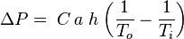
The combustion flue gases inside the flue gas stacks are much hotter than the ambient outside air and therefore less dense than the ambient air. That causes the bottom of the vertical column of hot flue gas to have a lower pressure than the pressure at the bottom of a corresponding column of outside air. That higher pressure outside the chimney is the driving force that moves the required combustion air into the combustion zone and also moves the flue gas up and out of the chimney. That movement or flow of combustion air and flue gas is called "natural draft (or draught)", "natural ventilation", "chimney effect", or "stack effect". The taller the stack, the more draft (or draught) is created.The equation below provides an approximation of the pressure difference, ΔP, (between the bottom and the top of the flue gas stack) that is created by the draft:
-
where: ΔP = available pressure difference, in Pa C = 0.0342 a = atmospheric pressure, in Pa h = height of the flue gas stack, in m To = absolute outside air temperature, in K Ti = absolute average temperature of the flue gas inside the stack, in K
The above equation is an approximation because it assumes that the molar mass of the flue gas and the outside air are equal and that the pressure drop through the flue gas stack is quite small. Both assumptions are fairly good but not exactly accurate.
The flue gas flow rate induced by the draft
As a "first guess" approximation, the following equation can be used to estimate the flue gas flow rate induced by the draft of a flue gas stack. The equation assumes that the molar mass of the flue gas and the outside air are equal and that the frictional resistance and heat losses are negligible:

| where: | |
| Q | = flue gas flow rate, m³/s |
|---|---|
| A | = cross-sectional area of chimney, m² (assuming it has a constant cross-section) |
| C | = discharge coefficient (usually taken to be from 0.65 to 0.70) |
| g | = gravitational acceleration at sea level, 9.807 m/s² |
| H | = height of chimney, m |
| Ti | = absolute average temperature of the flue gas in the stack, K |
| To | = absolute outside air temperature, K |
Designing chimneys and stacks to provide the correct amount of natural draft involves a great many factors such as:
- The height and diameter of the stack.
- The desired amount of excess combustion air needed to assure complete combustion.
- The temperature of the flue gases leaving the combustion zone.
- The composition of the combustion flue gas, which determines the flue gas density.
- The frictional resistance to the flow of the flue gases through the chimney or stack, which will vary with the materials used to construct the chimney or stack.
- The heat loss from the flue gases as they flow through the chimney or stack.
- The local atmospheric pressure of the ambient air, which is determined by the local elevation above sea level.
The calculation of many of the above design factors requires trial-and-error reiterative methods.
Governmental agencies in most countries have specific codes which govern how such design calculations must be performed. Many non-governmental organizations also have codes governing the design of chimneys and stacks (notably, the ASME codes).
Stack design
The design of large stacks poses considerable engineering challenges. Vortex shedding in high winds can cause dangerous oscillations in the stack, and may lead to its collapse. The use of helical faring is common to prevent this process occurring at or close to the resonant frequency of the stack.
Other items of interest
Some fuel-burning industrial equipment does not rely upon natural draft. Many such equipment items use large fans or blowers to accomplish the same objectives, namely: the flow of combustion air into the combustion chamber and the flow of the hot flue gas out of the chimney or stack.
A great many power plants are equipped with facilities for the removal of sulfur dioxide (i.e., flue gas desulfurization), nitrogen oxides (i.e, selective catalytic reduction, exhaust gas recirculation, thermal deNOx, or low NOx burners) and particulate matter (i.e., electrostatic precipitator)s. At such power plants, it is possible to use a cooling tower as a flue gas stack. Examples can be seen in Germany at the Power Station Staudinger Grosskrotzenburg and at the Rostock Power Station. Power plants without flue gas purification, would experience serious corrosion in such stacks.
In the United States and a number of other countries, atmospheric dispersion modeling studies are required to determine the flue gas stack height needed to comply with the local air pollution regulations. The United States also limits the maximum height of a flue gas stack to what is known as the "Good Engineering Practice (GEP)" stack height. In the case of existing flue gas stacks that exceed the GEP stack height, any air pollution dispersion modeling studies for such stacks must use the GEP stack height rather than the actual stack height.